Technical Support
For all GPON, EPON, fiber media converter, industrial switches and other products, we provide professional technical support, including email, telephone, online technical support, remote assistance, etc.
Contact information for the 7 x 24 technical support period.
Mobile number: +86 15712000724
Skype: allenker
Email: technical@htopto.com
---------------------------------------------------------------------------------------------------------------------------------------------
FAQ:
1. Common faults and troubleshooting methods of fiber media converter
2.Video optical converter FAQ
3. What is the difference between HGU, SFU, MDU, MTU and SBU?
4.What is the difference between EPON and GPON?
5. How to trouble shoot a Fiber Optic Transceiver
6. How to connect a IP Cameras/webcam?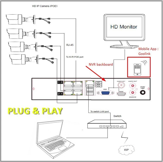
7.ITU 50GHz Center Wavelengths and Channel Numbering
8.Installing SFP and XFP Transceivers and GBICs
9.What's a watchdog? What is the purpose of a watchdog?
10. The Difference Between OM1,OM2,OM3 and OM4 Multimode Fibers
11.What is the difference among F/UTP,S/UTP,SF/UTP,S/FTP,F/FTP,U/FTP and U/UTP cables?
12. Fiber Optic Patchcord Production Flow
13. The basis for judging the compatibility of optical modules
1. Does it have the data diagnostic monitoring interface (DDMI) specified by SFF-8472 standard?
DDMI, also called DDM or DOM, has an alarm function when one or more data during the operation of the optical module exceeds the standard parameters specified by the manufacturer. The DDM function in optical modules provides a means of performance monitoring for systems that can help system management predict module life, isolate system failures, and verify module compatibility in field installations. If a compatible optical module has a data diagnostic monitoring function (DDM), it can be used to monitor the real-time parameters of the SFP optical module (including optical output power, optical input power, temperature, laser bias current and transceiver supply voltage, etc.) in order to quickly locate the fault location.
2. Does it pass compatibility verification?
Generally speaking, the higher the performance of the optical module, the stronger the compatibility. The compatibility of the optical module needs to be tested on the switch to check the working of the module, which is the only way to determine the good or bad performance of the optical module.
14. How to install and remove SFP/XFP modules?
15. 40G QSFP+ Optical Module with AOC/DAC Cable FAQ.
Q1: Can 40G optical modules be connected with 10G optical modules?
A1: Not all 40G optical modules can be connected with 10G optical modules, only 4*10G parallel transmission optical modules can be connected with 10G optical modules, for example: 40G multimode optical modules (QSFP+ SR4) can be connected with 10G 10G 10G multimode optical modules (SR) by using MPO-LC multimode OM3 fiber optic patch cables because they are both multimode optical modules and the wavelengths are all 850nm. 850nm, and 40G SR4 optical modules are backward compatible with IEEE 802.3ae 10GBASE-SR Ethernet protocol; 40G single-mode optical modules (QSFP+ PSM4) can be connected using MPO-LC single-mode OS2 fiber patch cords and 10G 10G single-mode optical modules (LR) because their wavelengths are 1310nm, and 40G PSM4 optical modules are backward compatible with IEEE 802.3ae 10GBASE-SR Ethernet protocol. optical modules are backward compatible with the IEEE 802.3ae 10GBASE-LR Ethernet protocol.
Q2: Where are 40G DAC high-speed cables used?
A2: 40G DAC high-speed cables are mainly used for transmission in data center cabinets, because high-speed cables do not use expensive optical devices and optical fibers as components, so the transmission distance is short and the price is low, which is very suitable for connecting servers and switches inside cabinets.
Q3: Can 40G and 10G ports be connected with cables?
A3: Yes, 40G AOC/DAC cables have QSFP+ to 4*SFP+ branch cables, which can interconnect 40G ports and 10G ports using these cables.
Q4:How many kilometers can 40G optical module transmit?
A4:Single-mode 40G QSFP+ ZR4 module can transmit up to 80 kilometers.
Q5:Does 40G optical module support both single and multi-mode fiber transmission?
A5: 40G QSFP+ LX4 optical module supports the use of multimode OM3/OM4 fiber patch cord transmission, up to 150 meters, also supports the application of single-mode OS2 fiber patch cord transmission, up to 2 km. Its interface type is dual LC, wavelength 1271, 1291, 1311, 1331nm, the use of LX4 can be adapted to the data center more flexible cabling.
Q6: Are there any more fiber-saving options for 40G multimode transmission?
A6: 40G SR4 needs to use at least 8-core multimode OM3 fiber for transmission, so it increases the cost of data center fiber cabling, but 40G multimode optical module is not the only SR4, there are also multimode PAM4 optical modules with PAM4 modulation technology, 40G BiDi optical modules, 40G SWDM4 optical modules, they are all multimode optical modules, the interface type is double LC They are all multimode optical modules with dual-LC interface type, and only need 2 cores of multimode OM3/OM4 fiber to achieve 40G rate transmission.
Q7:What are the types of 40G single-mode optical modules?
A7:The common 40G single-mode optical modules are 40G PSM4, 40G LR4, 40G ER4 and 40G ZR4. Among them, 40G PSM4 can transmit up to 2 kilometers, 40G LR4 can transmit up to 10 kilometers, 40G ER4 can transmit up to 40 kilometers, and 40G ZR4 can transmit up to 80 kilometers.
29.What is the difference between Cat6/Cat 6A/ Cat 7 network cables?
In the whole-house WiFi coverage project, the network cables often used are Cat5, Cat5E, Cat6.
However, with the upgrading of the integrated cabling industry, Cat5 and Cat5E network cables are beginning to be gradually eliminated by the market, and the current mainstream use of Cat6 network cable and Cat6A network cable, Cat 7 network cable in the home WiFi coverage application is relatively small, so today we will explore the difference between Cat6, Cat6A and Cat 7 network cable!
Difference between Cat6/Cat6A/Cat7 network cable:
Cat6 network cable: its transmission frequency of 1MHz ~ 250MHz, the transmission performance is suitable for applications with a transmission rate higher than 1Gbps
Cat6A network cable: also known as CAT.6A, the transmission frequency can reach a maximum of 500MHz, twice as much as Cat 6 cable, support for 10Gbps Internet access
There are two types of CAT6 cables, namely, unshielded CAT6 and shielded CAT6.
Cat 7 cable: 8 cores of pure copper, the transmission rate can reach 10Gbps, suitable for data centers and other occasions.
In Cat7 network cable, each pair of wires has a shielding layer, four groups of pairs of wires and a layer of shielding layer on the periphery, so its appearance is slightly thicker than the category 6 cable.
Generally speaking, Cat 6 or Cat6A network cables can already meet the basic transmission rate and frequency bandwidth requirements for home WiFi coverage, and Cat 7 cables are basically rarely used for ordinary home WiFi coverage cables.
What is the difference between Cat 6/Cat6A/Cat7 cables?
Different types of cables usually have relatively obvious distinguishing features, cat6 and cat6A cables have a cross-shaped internal "skeleton", cat7 cables have two layers of shielding.
In addition, you can also distinguish according to the logo on the outer skin of the cable, CAT.6 logo on the Cat 6 cable, CAT.6a logo on the Cat6A cable and CAT.7 logo on the Cat 7 cable.
How to choose a cable?
The choice of cable is based on the needs of the home WiFi environment, if it is a gigabit network, then the cable can be either a Cat6 cable or a Cat6A cable; if it is a 10Gb network, then you need to choose a Super Cat6/Cat 7 cable when wiring.
Of course, if the home WiFi environment is a gigabit network, but you want to upgrade the WiFi environment for the future to do "advance", then you can also lay the Cat6A cable.
30. Difference between OS1 and OS2 Singlemode Fiber
30.1, What are OS1 and OS2 single-mode fibers?
Both OS1 and OS2 fibers are single-mode fibers regulated by the ITU-T standard (i.e., ITU-T Recommendation, which describes the geometrical and transmission characteristics of single-mode and multimode fibers). In the ITU-T standard, OS1 single-mode fiber is a conventional single-mode fiber that conforms to the G.652.A and G.652B (conventional) fiber standards, while OS2 single-mode fiber is a single-mode fiber that conforms to the G.652C and G.652D fiber standards, and is also referred to as low-water-peak or zero-water-peak fiber, which is commonly used in CWDM networks. In addition, the latest ITU-T G.657A1 fiber standard specifies a bend-insensitive single-mode fiber with excellent bending resistance, and OS2 single-mode fibers compliant with this standard are now available from some fiber suppliers.
30.2, What is the difference between OS1 and OS2 singlemode fiber?
Standards: OS1 single-mode fibers typically meet ITU-T G.652 standards, including ITU-T G.652.A and ITU-T G.652B (conventional), ITU-T G.652C and G.652D (low water peak). OS2 single-mode fibers typically meet the fiber standards G.652C or G.652D, which are also referred to as single-mode zero-water-peak or single-mode low-water-peak fibers. OS2 single-mode fibers typically meet fiber standards G.652C or G.652D, also known as single-mode zero-water-peak fiber or single-mode low-water-peak fiber. In addition, the new cabling standard G.657.A1 was released for bend-insensitive singlemode fiber patch cords to optimize the cost/performance ratio of fiber optic products, and OS2 singlemode fibers compliant with this standard are available on the market today.
Cable Construction: OS1 singlemode fiber is usually tightly sleeved and designed for indoor applications, it usually has a protective sheath on the outside and a bundle of flexible fiber polymers (e.g., aramid yarns) wrapped around the middle. os1 singlemode fiber core and cladding are made of glass, which is unbendable and brittle, and the coating layer protects the fiber and extends its service life. os2 singlemode fiber is usually loosely sleeved and more suitable for outdoor applications, in some cases, it is more suitable for outdoor applications. OS2 singlemode fiber is usually loose sleeve design, more suitable for outdoor applications, in some extreme environments when deployed, requires more robust cable construction. OS2 singlemode fiber is spirally placed in a semi-rigid tube, so OS2 can be stretched without bending the inner fiber, so as not to destroy the fiber in the huge tensile force.
Attenuation value: The attenuation value of OS1 single-mode fiber is greater than that of OS2 single-mode fiber. Typically, OS1 single-mode fiber has a maximum attenuation value of 1.0db/km in the 1310nm and 1550nm bands, while OS2 has a maximum attenuation of 0.4db/km.
Transmission Distance: OS1 and OS2 single-mode fibers have different transmission distances; OS1 single-mode fiber has a maximum transmission distance of 10km, while OS2 single-mode fiber can reach a maximum distance of 200km. In addition to this, OS1 and OS2 single-mode fibers can achieve transmission rates from 1G to 10G at different distances, but OS2 single-mode fibers can be used for 40G/100G Ethernet transmission. 100G Ethernet transmission.
Application Scenarios: OS1 is typically used for shorter distance single-mode fiber applications such as data centers, local area networks (LANs), and internal enterprise applications. OS2 is suitable for longer distance single-mode fiber transmission and is commonly used in applications such as Wide Area Networks (WANs), long-distance communications, and long-distance network connectivity.
Overall, OS1 and OS2 single-mode fibers have their own advantages and applicable scenarios. Choosing the right type of fiber needs to be decided based on specific application requirements and environmental conditions. In practice, it is recommended to consult with our professionals to ensure that the most appropriate fiber optic solution is selected.
31,13 common questions about POE technology
In recent years, PoE power supply technology has been gaining momentum. With a series of advantages such as simplifying the installation and deployment of power equipment, energy saving, and security, PoE power supply has become the new favorite of wireless coverage, security monitoring, and smart grid and other scenarios. In the technical exchanges, engineers are most confused about the problem of POE power supply. This article summarizes the most concerned about the 13 questions, one by one to answer.
Question 1: What is PoE technology?
PoE (Power Over Ethernet) refers to the existing Ethernet Cat.5 cabling infrastructure without any changes in the case of some IP-based terminals (such as IP telephones, wireless LAN access points AP, network cameras, etc.) to transmit data at the same time, but also for such equipment to provide DC power supply technology. PoE technology can ensure that the existing structured PoE technology can minimize costs by securing existing structured cabling while keeping existing networks functioning properly.
A complete PoE system consists of a Power Sourcing Equipment (PSE) and a Powered Device (PD).
Power Sourcing Equipment (PSE): Ethernet switches, routers, hubs or other network switching devices that support POE.
Powered Device (PD): In the monitoring system is mainly the IPC (Internet Protocol Camera).
Question 2: How to choose a PoE switch?
1. How much power do you need to supply to the device: PoE switches use different standards, the output power will be different, for example: IEEE802.3af maximum not more than 15.4W, due to the loss of the transmission line material, it can supply power to the device with a maximum power consumption of not more than 12.95W. PoE switches following the IEEE802.3at standard can supply power to devices with a maximum power consumption of up to 25W. 2.
2. How many devices can be powered at most: An important indicator of a PoE switch is the total power supplied by PoE. Under the IEEE802.3af standard, if the total PoE power of a 24-port PoE switch reaches 370W, it will be able to supply power to all 24 ports (370/15.4=24), but if it is calculated in accordance with the maximum single-port power supply power of 30W of the IEEE802.3at standard, at the same time, it will only be able to supply power to 12 ports at most (370/30=12). 3. 12). 3. the number of interfaces required, whether with fiber optic port, with or without network management, rate (10/100/1000M).
Question 3: Is PoE power supply stable?
From a technical point of view, PoE technology has been developing for many years, and is now in a very mature stage, the standard PoE power supply is stable and safe enough. However, due to cost pressures in the current monitoring market, the selection of PoE switches or wire quality is too low, or program design itself is unreasonable, the power supply distance is not arranged or connected to too many high-power devices appear to be insufficient power supply (especially at night when the monitoring equipment to open the heating mode). So there is a common view that PoE power supply is not stable.
Network monitoring projects, unlike ordinary network cabling, data transmission is very large, high power, and requires uninterrupted work around the clock, the use of quality assurance of PoE equipment and wire is a guarantee of the stability of the entire system.
Question 4: Is PoE-powered switch energy-saving?
As we all know, one of the major advantages of PoE power supply is energy saving, but what exactly is energy saving embodied in? Take MS series standard PoE-powered switches as an example, PoE-powered switches will automatically adjust the power according to the power supply equipment. For example, when the temperature of an infrared dome is low, the power of the heating function reaches 30Wmax, while the normal power is 24Wmax, and the PoE switch will automatically adjust the power supply according to the running condition of the dome.MS series standard PoE switches can set the PoE power supply cycle, which can automatically stop supplying power to terminals on specified ports on vacations and during nighttime, which not only saves energy but also sets a flexible usage mode under certain scenarios. MS series standard PoE switches can monitor all ports in real time, and if the status of a port is down, the system will automatically stop supplying power to the port and enter into the energy-saving mode, which not only saves energy, but also ensures the stable operation of normal equipment.
Question 5: Is more power better for PoE powered switches?
Due to the emergence of high-power devices such as HD dome, real-time video phone, etc., network equipment vendors are scrambling to develop PoE switches with higher total power. However, many products only pursue the increase in total power, ignoring the relationship between power and the number of ports, in the power at the same time, will inevitably result in an increase in the overall cost of the equipment, the result is that the user chooses the PoE switch utility is not strong, low cost-effective. Therefore, in the actual deployment, you should first determine the power and number of PD devices and choose the most suitable PoE switch.
Question 6: Advantages of PoE power supply program?
1. Simplify wiring and save labor cost
A network cable transmits data and power supply at the same time, PoE makes it no longer need expensive power supply and time consumed by installing power supply, saving costs and time.
2.Safety and Convenience
PoE powered end devices will only supply power to the device that needs it. Voltage is only present on the Ethernet cable when the device that needs it is connected, thus eliminating the risk of power leakage on the line. Users can safely mix legacy and PoE devices on the network, which are able to coexist with existing Ethernet cables.
3. Easy Remote Management
Like data transmission, PoE can be supervised and controlled by using the Simple Network Management Protocol (SNMP) to monitor and control the device. This feature can provide functions such as nightly shutdowns and remote reboots
Question 7: What are the disadvantages of PoE power technology in engineering applications?
1. Insufficient power, the receiving end can not be carried: 802.3af standard (PoE) output power is less than 15.4W, for the general IPC is enough, but for the ball and other high-power front-end equipment, the output power does not meet the requirements. 2.
2. Risk is too centralized: In general, a PoE switch at the same time to multiple front-end IPC power supply, any failure of the switch's POE power supply module will lead to all the cameras can not work, the risk is too centralized.
3. equipment, maintenance costs are high: compared to other power supply methods, PoE power supply technology will increase the after-sales maintenance workload, from the sense of security and stability, separate power supply stability, security is the best.
Question 8: The safe transmission distance of PoE power supply? How to choose the network cable?
The safe transmission distance of POE power supply is 100 meters, and it is recommended to use Super Category 5 all-copper network cable.
It is possible to transmit DC power over a long distance with standard Ethernet cables, so why is the transmission distance limited to 100 meters?
The fact is that the maximum transmission distance of PoE switch mainly depends on the data transmission distance, when the transmission distance is more than 100 meters data delay, packet loss and other phenomena may occur. Therefore, in the actual construction process, the transmission distance is best not to exceed 100 meters.
However, there are already some PoE switches with a transmission distance of up to 250 meters to meet the long-distance power supply. It is also believed that soon with the development of PoE power supply technology, the transmission distance will be extended to a greater distance.
POE power supply cable requirements of this issue only in China and other fake cheap goods rampant in the country is a problem, in many developed countries is not a problem. POE IEEE 802.3af standard requires PSE output port output power of 15.4W or 15.5W, transmission of 100 meters after the PD device must accept the power is not less than 12.95W, in accordance with the 802.3af typical current value of 350ma calculation, the power must not be less than 12.95W. According to the 802.3af typical current value of 350ma calculation, 100 meters of cable resistance must be (15.4-12.95W)/350ma = 7 ohms or (15.5-12.95)/350ma = 7.29 ohms. And standard network cable is naturally fulfills this requirement, the IEEE 802.3af poe power standard itself is measured in standard network cable. And only so will produce POE power supply cable requirements of this issue, because many of the market are non-standard cable, not strictly in accordance with the requirements of the standard cable to produce. The market of non-standard network cable materials are mainly copper-clad steel, copper-clad aluminum, copper-clad iron, etc., the resistance value of these cables is large, are not suitable for POE power supply. POE power supply must use oxygen-free copper cable, that is, the standard network cable.
PoE power supply technology has high requirements for wire, it is recommended that in the monitoring project, do not save cost on the wire, the loss is not worth it.
Question 9: Should I buy a non-standard or standard PoE powered switch?
To not non-standard or standard, this mainly depends on, to power the AP, IP Camera is to support 48V, 24V or 12V input? If it is 48V, it is written that it supports IEEE802.3 AT or AF power supply standard, which is generally standard. If it is 24V and 12V powered devices, you need to find the corresponding 12/24V non-standard power supply switch, or you can buy the standard one, then you need to buy a PD powered splitter, which will convert the PoE into DC power supply and network cable data.
Then why is it still more recommended to buy the standard one, because there are many hidden problems!
The working principle of non-standard PoE-powered switch is to belong to the switching power supply category, no PoE chip, just through a transformer will 220V AC power step-down to 48V DC, do not detect the lower end of the powered device, directly in each RJ45 port uninterrupted output voltage and current, which may lead to excessive voltage, burned the lower end of the powered device. Such a device can not be directly connected to other network equipment, because the direct connection is easy to lead to the PoE power supply inside the network cable 2 pairs of wires, positive and negative poles are connected to form a short circuit, the port is damaged, or smoke and fire, which can easily cause accidents and potential hazards.
To summarize, the standard PoE-powered switch inside the PoE control chip, before the power supply has the function of detection, when the device is connected, the PoE power supply will send a signal to the network to detect whether the terminal in the network is to support PoE power supply PD equipment. The non-standard PoE product is a strong supply-type network power supply device, a power supply that is powered, there is no detection step, regardless of whether the terminal is a PoE powered device are powered, it is very easy to burn the access device.
Question 10: How to distinguish between standard PoE and non-standard PoE?
1, look at the specifications, if the output is 12-24V, then it is certainly non-standard.
For example, the following picture of this machine, a treasure 8-port 6-port POE power supply switch; but look at the specification parameters written, 15V1A output, 19V1A ultra-long-distance output. Because the IEEE802.3 AT/AF protocol provides that the standard PoE port output
Voltage range is between 44-57V, so this at a glance know that is non-standard, so cheap is not surprising, because the manufacturer in order to save costs to PoE chip is also eliminated. But if the port output 48V, it must be a standard PoE switch? Not necessarily, we have to use the second trick.
2, use a multimeter to detect the corresponding wire sequence of the port or cable, and test whether the cable is always outputting voltage.
Start the device, the multimeter to the voltage measurement gear, with the multimeter two pens were touching the PSE equipment power supply foot (usually RJ45 port 1/2, 3/6 or 4/5, 7/8), if measured 48V or other voltage values (12V, 24V, etc.) stable output devices that are non-standard products. Because in this process, PSE does not test the powered equipment (here is a multimeter), and directly use 48V or other voltage values to supply power.
On the contrary, if the voltage is not measured and the multimeter needle jumps between 2~10V, it is a standard POE. because at this stage, the PSE is doing detection on the PD side (here is the multimeter) and the multimeter is not a legitimate PD, the PSE will not supply power, and there is no stabilized voltage generated.
If it is a standard PoE power supply device, when it supplies power to the following devices, it will send a small voltage to detect whether there is a corresponding powered device connected to the following; and then according to the power required by the following devices to provide the corresponding voltage and current. Figure 2 below this PoE power supply switch although written 48V output, but it and other non-standard PoE switch, in fact, belongs to the class of switching power supply, no PoE chip.
Have done monitoring and wireless engineering contractor friends know that the reliability of engineering products is very important; low reliability, the reliability of the entire system is even lower, which not only affects the company's business development, but also to the engineering contractor to increase the cost of maintenance of the system is very great, and some can not even acceptance, resulting in serious losses.
Question 11: Is the reliability of a standard PoE-powered switch necessarily high?
The reliability of the equipment and the use of bad environment there is a close relationship between the commercial switch is generally used indoors, industrial switches are generally used outdoors, the reliability requirements are not the same, here we tentatively take the commercial switch as an example. The reliability of commercial POE switches is mainly composed of two parts, one is the switching part, which is mainly composed of (PCB, switch chip + PoE chip, other electronic materials), and the other part is the power supply with built-in and external power supply for POE. Because the power supply is responsible for the whole power supply, its reliability is the most important. Here we also briefly say the engineer friends to determine the reliability of POE power switch power supply three relatively simple program:
a. Carefully check whether the power supply above the 3C certification and corresponding manufacturer information we still have the power supply of the above equipment, we look at, there are a lot of certification labels labeling, which is familiar with electronic equipment, may find that the power supply actually does not have 3C certification, wow not much to say, so it is not knowing the law? Dare not say more, there is no 3C certification, there is no manufacturer, is not the three no well. Such a power supply can be concluded immediately, the quality is unlikely to be good, not to mention the long-term 24-hour uninterrupted power supply to the following equipment to use.
Many PoE miscellaneous manufacturers on the market, obviously three products, but still in the power supply labeled 3C, UL, GS so many certifications. These are labeled by the manufacturers, added to their own. That for this kind of how to do it, how do we do it?
b. Test the surface temperature of the power supply
The actual test full load stabilization, if the chassis is stable over 50 degrees, then there is a great risk. We look at the specifications on the power supply, power supply 48V2A, the conversion should be 96W, but the power supply is actually the maximum power consumption is written 120/240W, power supply design have a threshold, more than this power after the power supply will be restarted, long-term overloaded operation, the life of the power supply will become shorter, resulting in decreasing reliability. So with such a power supply switch will be a high rate of repair, more terrible is that these power supplies actually do not do any lightning protection measures, encountered a thunderstorm, the product may be a bad piece of ah.
The reason why manufacturers use such a power supply, because the power supply is the main part of the cost of POE switches, manufacturers in order to save costs, the use of low-quality power supply, vicious competition, total disregard for the quality of the product. Now we know how to choose a real cost-effective PoE powered switch.
Question 12: How many APs and IP Cameras can a PoE-powered switch carry?
For example, the following 5-port 100Gb/s 4-port PoE-powered switch, TEF1105P-4-63W, can be found in the official website and the specification of its PoE maximum output power of 57W, in the end, how many Hikvision 300W pixel day/night dome network cameras can be connected? You can first go to the official website of Hikvision to find the corresponding DS-2CD2135F(D)-I(W)(S), the following chart in its detailed parameters in the column to find the power consumption options: 5W MAX (when ICR switching 7W), ICR is the meaning of the night infrared.POE maximum output power / maximum consumption of the camera to arrive at the maximum number of support, 57W/7W, is equal to 8, because the POE power supply port is only 4, so it is only the POE power supply Port only 4, so only support 4, and others are similar.
Careful friends may find that, no, you did not count the loss of the network cable above ah. Indeed, the loss of network cable above the main current * resistance of the cable, so the poorer the quality of the cable, the greater the loss, so we do this using the eight-core power supply, 51V output, increase the voltage, eight-core parallel circuit shunt design, reduce the current transmitted by the network cable to reduce the loss, and at the same time can be supported to more powered devices. Even if the poor quality network cable, can support 250 meters of long-distance transmission and power supply, to solve the monitoring wiring, part of more than a hundred meters need to deploy extenders, fiber optic and other costly wiring.
Question 13: How to choose PoE switches for security monitoring and wireless coverage?
PoE switch types are very many, from 100 megabytes to gigabit, and then to the full gigabit, as well as the difference between unmanaged and managed, a variety of different port number of differences, want to choose the right switch, you need to fully integrated consideration. To need high-definition monitoring project as an example of analysis.
Step 1: Choose a standard PoE switch
Step 2: Choose 100Gb or Gigabit switch
In the actual program needs to be integrated into the number of cameras, camera resolution, bit rate, frame rate and other parameters selected. Like Hikvision, Dahua and other mainstream surveillance equipment manufacturers provide professional bandwidth calculation tools, users can use the tools to calculate the required bandwidth, so as to select the appropriate PoE switch.
Step 3: Select af or at standard PoE switch
Choose according to the power of the monitoring equipment. For example, if you use a famous brand camera with 12W max power, you need to choose af standard switch. The power of a HD dome is 30W max, in this case, you need to choose at standard switch.
Step 4: Select the number of ports of the switch PoE switches
According to the different number of ports can be divided into 4, 8, 16 and 24 ports and so on several kinds, can be integrated monitoring equipment power, number, location, switch power supply and price selection.
32. Serial communication standards differences among RS232, RS485, RS422
Many engineers often RS-232, RS-422, RS-485 known as the communications protocol, in fact, this is not true, they are only about serial communications on a mechanical and electrical interface standards (at best, the physical layer of the network protocol), not a communications protocol, and what are the differences between them:
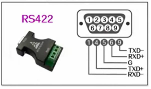
The first difference, the hardware pin interface definition is different:


The second difference, different ways of working
RS232: 3-wire full duplex
RS485: 2-wire half-duplex
RS422: 4-wire full duplex
The third difference, the communication mode is different
RS232: can only realize point to point communication
RS485: can realize point-to-multiple master-slave communication
RS422: can also realize point-to-multiple master-slave communication
The fourth difference, different logic characteristics
RS232: Logic "1" : -3V ~ -15 V; Logic "0" : +3V ~ +15 V
RS485: Logic "1" : +2V ~ +6 V; Logic "0" : -2V ~ -6 V
RS422: logic "1" : +2V ~ +6 V; logic "0" : -2V ~ -6 V
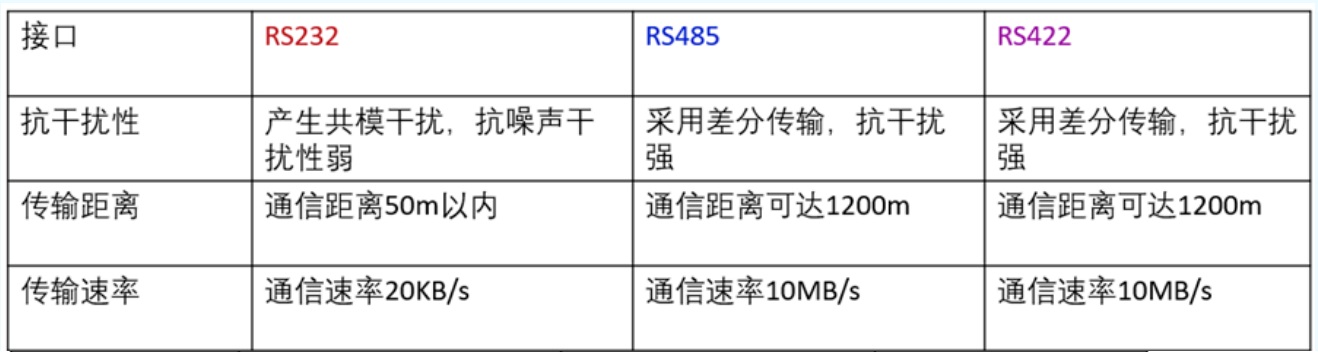
The fifth difference, anti-interference, transmission distance and transmission rate are also different
Comparison of RS-232 and RS-485
Anti-interference: RS485 interface is a combination of balanced driver and differential receiver, good anti-noise interference, RS232 interface using a signal line and a signal return line and constitute a common ground transmission form, this common ground transmission is prone to common mode interference.
Transmission distance: RS485 interface maximum transmission distance standard value of 1200 meters (9600bps). RS232 transmission distance is limited, the maximum transmission distance standard value of 50 meters, in fact, can only be used in about 15 meters.
Communication capability: RS-485 interface on the bus is allowed to connect up to 128 transceivers, users can use a single RS-485 interface to easily establish a network of devices. rS-232 only allows one-to-one communication.
Transmission rate: RS-232 transmission rate is lower, in asynchronous transmission, the baud rate is 20Kbps. the maximum data transmission rate of RS-485 is 10Mbps.
Comparison of RS-422 and RS-485
1, RS-422 has four signal lines: two transmit (T+, T-), two receive (R+, R-). Because the RS-422 receive and send are separate so can receive and send at the same time (full duplex).
2, RS-485 only two data lines: transmit and receive are A and B. Because RS-485 receive and transmit are shared two lines, so can not receive and send at the same time (half-duplex).
33、How to choose Copper SFP module, SFP optical module, DAC, AOC?
RJ45/Copper SFP module is a module that transmits through copper cable (e.g., twisted pair network cable), and is also a kind of optical module, the full name of the optical port to electrical port module.
With the rapid development of communication technology, a variety of communication interfaces have sprung up, of which the copper SFP module, optical module, DAC direct copper cable and AOC active optical cable has become the industry's popular choice. Each of these interface modules has its own specialty, and they play an important role in different scenarios. In order to better meet the communication needs, we need to have a deep understanding of their features and advantages in order to make a wise choice in practical applications. Next, this article will focus on the comparison between electrical interface modules, optical modules, DACs and AOCs (taking 10G as an example) to help readers better understand and choose the right communication interface module for them.
Copper SFP Module VS Direct Attached Copper (DAC)
Both ECM and DAC are suitable for short distance transmission applications, and both transmit over copper cable. However, the transmission distance of the copper SFP module is larger than that of the DAC. The transmission distance of the DAC is generally less than 7 meters, while the electrical interface module can transmit up to 30 meters.
Copper SFP Module VS Active Optical Cable (AOC)
The copper SFP module uses copper cable for transmission while the AOC uses fiber optic cable, so the electrical port module has a longer transmission distance of up to 300 m. The AOC active optical cable offers enhanced signal integrity and flexibility in deployment, and better air flow heat dissipation in the server room cabling system, but it costs more than copper cabling at 10G rates.
Copper SFP VS SFP Optical Modules
Compared with SFP optical modules, electrical port modules use copper cabling for cabling, while optical modules require fiber optic cabling. If the original cabling system is copper, RJ45 port/copper SFP modules can reuse the previous copper cabling resources to complete the 10G network deployment. In terms of transmission distance, the electrical interface module transmission distance is closer, optical module according to different combinations, the transmission distance can be as high as 120km.
The RJ45 port/copper SFP module is a kind of module that transmits through copper cable (for example, twisted pair network cable), and it is also a kind of optical module, the full name is optical port to electric port module.
With the rapid development of communication technology, a variety of communication interfaces have sprung up, of which the electrical interface module, optical module, DAC direct copper cable and AOC active fiber optic cable have become the industry's popular choice. Each of these interface modules has its own specialty, and they play an important role in different scenarios. In order to better meet the communication needs, we need to have a deep understanding of their features and advantages in order to make a wise choice in practical applications. Next, this article will focus on the comparison between electrical interface modules, optical modules, DACs and AOCs (taking 10G as an example) to help readers better understand and choose the right communication interface module for them.
RJ45 port/copper SFP VS Direct Attached Copper (DAC)
Both ECM and DAC are suitable for short distance transmission applications, and both transmit over copper cable. However, the transmission distance of the electrical interface module is larger than that of the DAC. The transmission distance of the DAC is generally less than 7 meters, while the electrical interface module can transmit up to 30 meters.
RJ45 port/copper SFP VS Active Optical Cable (AOC)
The electrical port module uses copper cable for transmission while the AOC uses fiber optic cable, so the electrical port module has a longer transmission distance of up to 300 m. The AOC active optical cable offers enhanced signal integrity and flexibility in deployment, and better air flow heat dissipation in the server room cabling system, but it costs more than copper cabling at 10G rates.
RJ45 port/copper SFP VS SFP Optical Modules
Compared with optical modules, RJ45 port/copper SFP use copper cabling for cabling, while optical modules require fiber optic cabling. If the original cabling system is copper, RJ45 port/copper SFP can reuse the previous copper cabling resources to complete the 10G network deployment. In terms of transmission distance, RJ45 port/copper SFP transmission distance is closer, optical module according to different collocation, the transmission distance can be as high as 120km.
34. What is the difference between G.652.D, G.657.A1, G.657.A2 single mode fiber?
In the field of optical communication, fiber specification is one of the most important factors to ensure network performance and application stability.G.652.D, G.657.A1, G.657.A2 are three common fiber specifications, which are different in terms of transmission characteristics, applicable environments and performance. This article will delve into the definitions and characteristics of these three specifications, as well as their differences and advantages and disadvantages in practical applications.
G.652.D fiber specification
G.652.D fiber is a single-mode fiber specification widely used for long-haul communications and metropolitan area networks. Its core characteristics include:
Low Transmission Loss: G.652.D has low transmission loss, making it suitable for scenarios that require wide-area transmission, such as international and cross-country communications.
Medium Bandwidth: Although not as wide as some emerging specifications, G.652.D performs well in most transmission scenarios.
Legacy OD: G.652.D fiber typically has an OD of 125 microns, which is consistent with legacy standards.
G.652.D is widely used for high-speed data transmission in communications networks that span large regions. For example, backbone networks connecting international data centers often use G.652.D fiber to ensure that data is transmitted in an efficient and reliable manner.
G.652.D also excels in Optical Amplifier applications. This fiber maintains signal strength over long distances and is suitable for the core backbone of fiber optic communications.
G.657.A1 Fiber Specifications
G.657.A1 fiber is a specification designed for special cabling environments and its core features include:
Bend Radius Advantage: G.657.A1 has a small bend radius, making it suitable for cabling environments that require a high degree of bend, such as FTTH (Fiber to the Home) applications within homes and businesses.
Superior Mechanical Properties: G.657.A1 fiber excels in mechanical properties, making it more suitable for scenarios that require frequent connections and bends.
Inside homes and businesses, G.657.A1 is widely used for FTTH cabling, especially in scenarios that require traversing curved areas. This fiber can more flexibly adapt to corners and bends, ensuring that signal quality is not compromised.
G.657.A1 is suitable for bringing fiber optics into homes and businesses, especially in limited spaces, enabling more flexible installations through the advantage of its bend radius.
G.657.A2 Fiber Specification
G.657.A2 is a specification that builds on G.657.A1, with key features including:
Smaller Bend Radius: G.657.A2 has a smaller bend radius than G.657.A1, making it more suitable for scenarios where space constraints and bending requirements are more demanding.
Optimized Mechanical Properties: G.657.A2 is further optimized in terms of mechanical properties, providing better connection and bending performance.
G.657.A2 is commonly used in fiber optic access networks, especially when it is necessary to bring fiber inside buildings. Its smaller bend radius makes it easier to route fiber optic cables in limited spaces.
In some compact space cabling scenarios, such as inside a data center, G.657.A2 can better fit into the limited cabling space and provide a more flexible cabling solution.
Comparison
Transmission Performance Comparison
G.652.D: Suitable for long distance transmission with low transmission loss but medium relative bandwidth.
G.657.A1: Performs well over typical transmission distances, but has a slight compromise compared to G.652.D. Smaller bend radius for specific wiring environments.
G.657.A2: Transmission performance between G.652.D and G.657.A1, more suitable for some specific wiring scenarios.
Bending Performance Comparison
G.652.D: Relatively poor bending performance, suitable for more straight wiring.
G.657.A1: Smaller bending radius, suitable for FTTH and other scenarios that require a high degree of bending.
G.657.A2: Better bending performance, suitable for limited space and high bending requirements of the cabling environment.
Mechanical Comparison
G.652.D: Average mechanical properties, suitable for traditional communication scenarios.
G.657.A1: Good mechanical performance, suitable for frequent connection and bending environments.
G.657.A2: Further optimized on the basis of G.657.A1 to provide better mechanical performance.
Conclusion:
Considering the characteristics of the three fiber optic specifications G.652.D, G.657.A1 and G.657.A2, we can draw the following conclusions:
G.652.D is the more appropriate choice for environments requiring long distance transmission and general communications.
In environments where frequent connections and bends are required, G.657.A1 has a clear advantage.
G.657.A2 is further optimized on the basis of G.657.A1, and performs even better in some scenarios with limited space and high bending requirements.
The final choice depends on the specific application requirements. In practical applications, the most suitable fiber specification can be selected based on factors such as network layout, environmental requirements and budget to ensure network performance and reliability.